Understanding Wire Size, Fuse Size, and Connection Diagrams
- 28 February 2024
- 2123 views
- No Comments
Follow the inverter wiring guidelines to understand the wire size, fuse size and connection diagrams with EPEVER.
Table of Contents:
· Introduction to Cable Types
· Wire Connectors: A Closer Look
· Protection Devices
· Tips for Wire Size Calculation
· Wire and Fuse Size Calculation: A Simple Example to Illustrate
· Understanding Communication Wires
· Basics of Connection Diagrams
It’s important to remember that each off-grid system can be different. Many factors will influence your decisions. Safety should always be your main concern. Always follow the guidelines set by local electrical standards and, if unsure, consult with a professional electrician to ensure everything is set up correctly.
Let’s dive in!
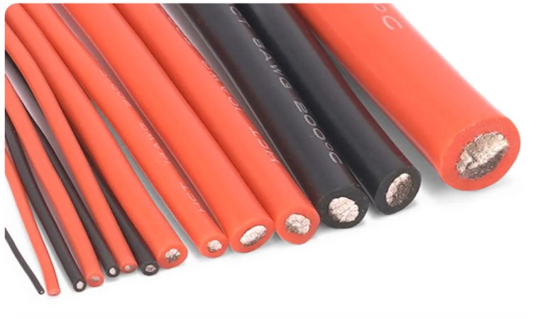
Understanding Different Cable Types and Their Appropriate Use in DC and AC Sides:
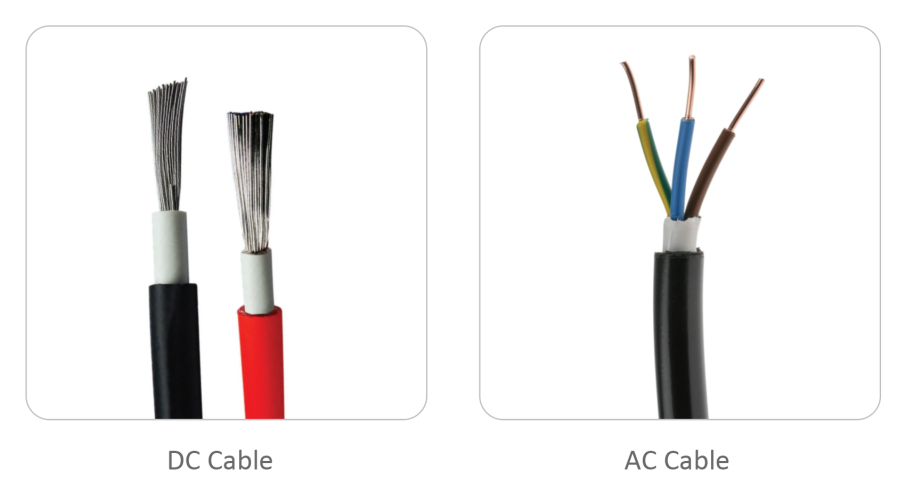
1. DC vs AC Cables:
DC cables differ significantly from AC cables in terms of construction, strand composition, installation requirements, and size. In essence, each is tailored for distinct purposes. For instance, on the DC side, we avoid utilizing stranded, non-flexible, and AC cables.
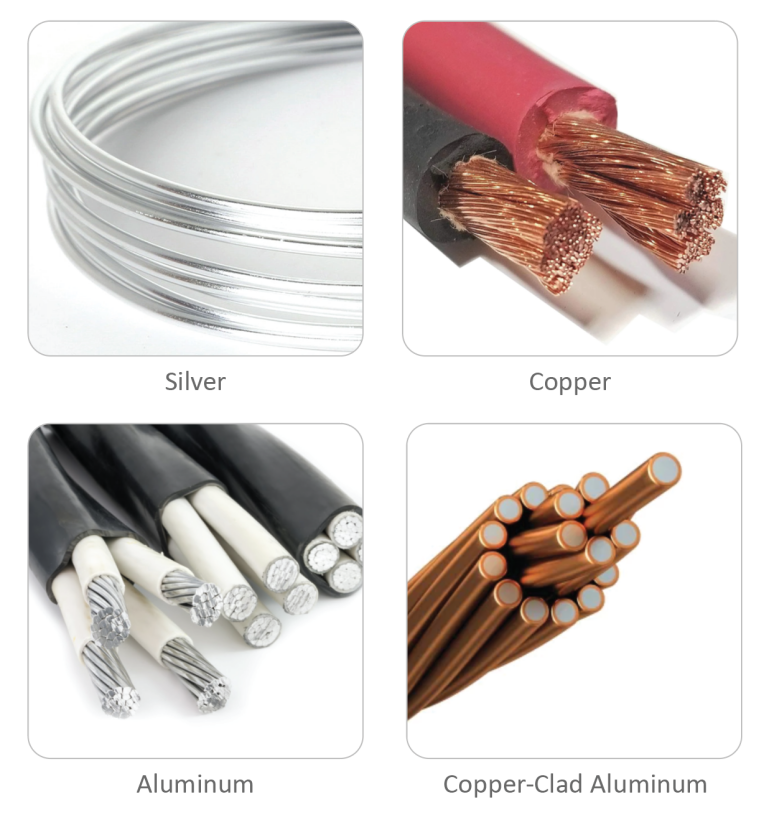
2. Cable Materials: Silver, Copper, and Aluminum
· Silver: The premier conductor is silver, but its high cost makes it unsuitable for solar applications.
· Copper: The most prevalent conductor for solar applications is pure copper due to its excellent conductivity.
· Aluminum: While more affordable than copper, aluminum does not conduct electricity as effectively, resulting in increased energy loss through resistance. Beware of copper-clad wires in the market; they’re aluminum at their core. Aluminum cannot handle the same current as copper. Consequently, with aluminum or copper-clad aluminum wires, you’ll experience restricted current. The differing contraction rates between copper and aluminum can lead to cable breakage over time, escalating resistance, overheating at the joints, and even potential fire risks.
3. Installation Conditions: Different conditions dictate specific cable types:
· High temperatures:
High temperatures Opt for heat-resistant cables.
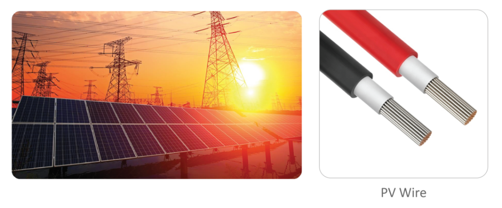
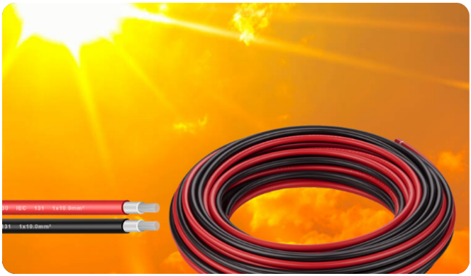
Use THHN cables for indoor settings, USE2 or RHW2 cables beneath solar panels, and PV wires explicitly designed for solar applications.
· Moisture, Marine, or Damp Environments: Water-resistant or marine-grade cables are recommended.
· UV Radiation Exposure: If a cable is directly exposed to sunlight, like on a van roof, it’s vital to use a UV-resistant insulated cable. Failing to do so can result in system leakage, short circuits, or even fires. Remember, a wire’s capacity is influenced by temperature and insulation type. Always refer to the wire manufacturer’s guidelines for temperature adjustments and choose a wire apt for your specific installation conditions.
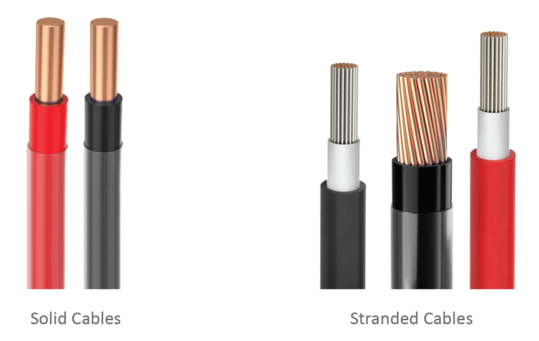
4. Cable Flexibility: Solid vs. Stranded Cables can be of solid core or stranded construction. Stranded wires, with more surface area for current flow, often provide superior conductivity than solid core ones. Stranded cables, being more flexible, are generally preferable for solar power systems.
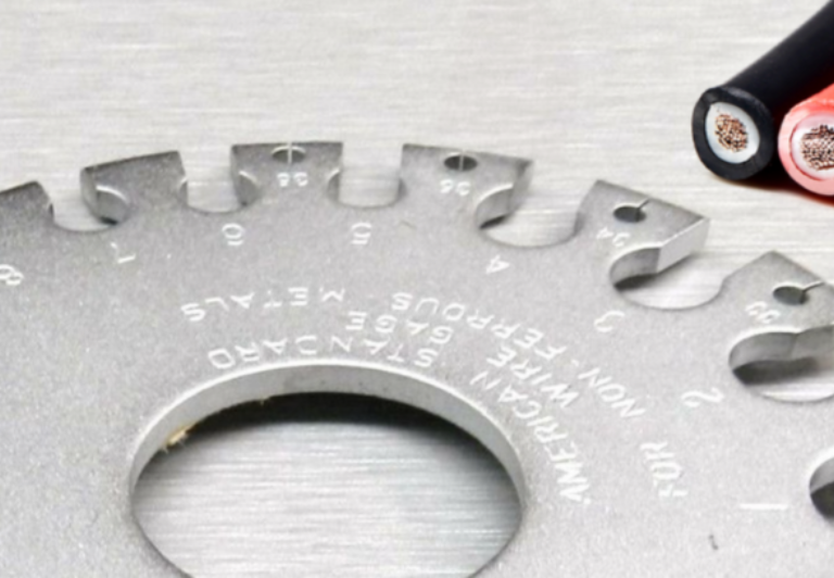
5. Wire Gauge (Thickness) and Length: These parameters dictate the amount of current a wire can safely transport. A longer, thinner wire will present more resistance to current flow. If this resistance becomes too elevated, it can result in significant energy losses or even electrical fires
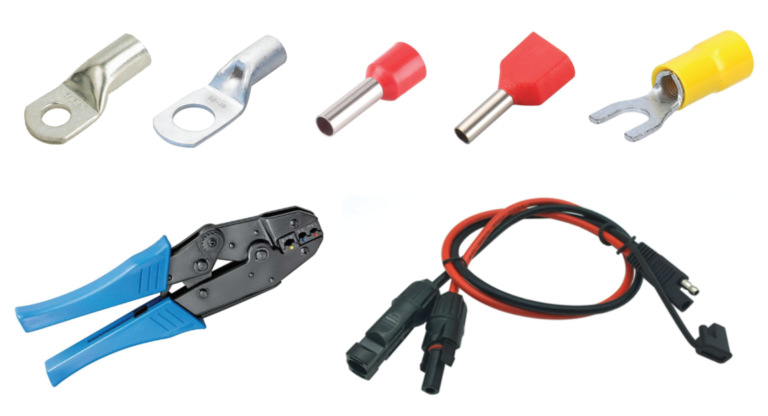
Besides cables, some elements are needed such as washers, strings, cable lugs, nuts, thermal strings, etc. Cable lugs are used to connect a cable to a bolt and it can be a battery bolt or a bolt on a busbar and a cable lug need to match the cable thickness.
· The precision with which insulation is removed from the cable is crucial. Use specialized stripping tools for this purpose.
· The tools employed for securing connectors are equally vital. Using inappropriate tools, such as hammers, can lead to inadequate contact between the wire and the block. This can result in high resistance at the junction, leading to overheating and subsequent failures.
· It’s essential to ensure that connections are moisture and water-resistant. Failure to do so can result in cable corrosion over time. As corrosion progresses, resistance increases, causing further overheating.
· Every detail matters in installation to ensure longevity and optimal performance.
· Ensure that when attaching cable lugs to the mounting surface, there are no obstructions between the lug and the surface. Both should be in perfect alignment.
· The tightening torque is pivotal. Over-tightening can damage the lug or the wire. Using a tool with a preset torque can help maintain consistent resistance across connectors.
· Achieving a balanced battery connector is crucial. Lugs must be tightened uniformly. If there’s a disparity in the tightness – one being overly tight and another being too loose – it leads to uneven contact with the bus bars, resulting in varied resistance levels. This discrepancy is termed as an imbalance in battery connectors. Consistency in cable length, ports, connectors, washers, and nuts is essential for optimal performance.
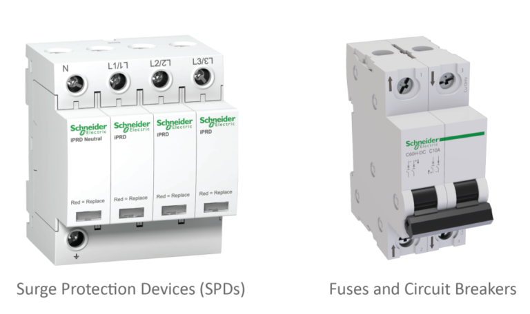
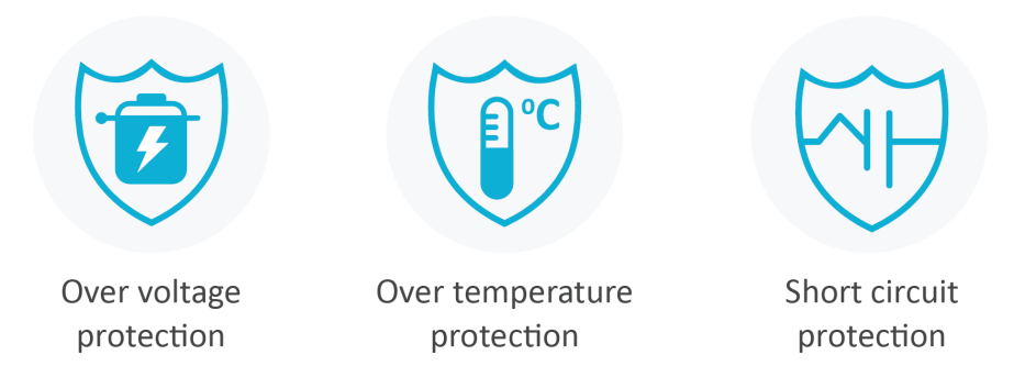
Solar system protection is a multi-layered approach, ranging from surge arrestors to circuit breakers and fuses safeguarding the equipment. Adhering to this multi-tiered strategy is essential for system safety, as each layer addresses specific surge energy levels. While surge arrestors and lightning systems handle high surge currents, selecting the appropriate fuse and wiring size are equally crucial. Typically, the current rating should be set at 1.2 times the system’s maximum current.
Selecting the correct cable size is pivotal for ensuring the safety and efficiency of an off-grid system. Factors such as maximum current, allowable voltage drops or distances, and specific equipment specs are fundamental.
· Reference Product Manual or Technical Specifications: Always start by referring to the product manual or technical datasheet of your inverter or charge controller. Manufacturers often provide recommended wire sizes for specific models.
· Maximum Current: For both DC and AC power, you need to find out the maximum current.
· Voltage drop: Strive for a voltage drop below 3% for DC and 5% for AC.
· Determine Cable Size using Online Tools: There are online calculators that can help you decide the right wire size which considers maximum current, allowable voltage drop, cable run distance, ambient temperature, and some other parameters.
· Unique Equipment Specs: Different inverters and batteries have specific requirements for wire sizes. Ensure that the cable size meets or exceeds these requirements.
· Wire Insulation and Right Covering: When selecting insulation, account for environmental factors, such as needing UV resistance and always remember to adhere to local regulations.
· Thicker cables on the DC and AC side: Thicker cables on the DC side usually perform better. For the AC side, the optimal choice might vary based on the number of inverters and their configuration.
· Ambient Temperature Correction: The temperature of the environment where the cable is installed affects its capacity to carry current. Higher temperatures decrease the wire’s current-carrying capability. Refer to correction factors provided by wire manufacturers or standards.
· Safety and Regulatory Compliance: Ensure all selections adhere to local electrical codes, standards, and regulations. This might include considerations for overcurrent protection, grounding, and more.
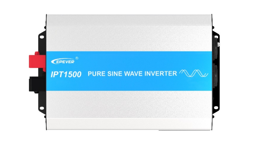
Using the EPEVER IPT1500-22 inverter as an illustration, we’ll determine the suitable wire and fuse sizes for both DC and AC sides:
System Current = [Total power of the system ÷ system voltage (VDC or VAC)] × safety factor(1.5 for copper conductor)
Formula:
Notes:
· For DC calculations, use VDC; for AC, use VAC.
·Typically, a safety factor of 1.5 is used for copper. Adjust for other wire materials like aluminum.
Specifications:
· Total Load Power:1350W
· Output Voltage: 230 V AC
· Input Voltage: 24V DC
· Conversion Efficiency: 0.9
1. Calculating System Current:
· DC current: Total Load Power ÷ Input Voltage ÷ Conversion Efficiency =1350 ÷ 24 ÷ 0.9= 62.5A
· DC fuse current: DC Current × Safety Factor = 62.5 × 1.5 = 93.75 A
· AC current: Total Load Power ÷ Output Voltage =1350 ÷ 230 ≈ 5.87 A
· AC fuse current: AC Current × Safety Factor = 5.87 × 1.5 ≈ 8.8 A
2. Allowable Voltage Drop:
· DC input side: 3%
· AC output side: 5%
3. Determining Wire Size (based on a typical wire sizing calculator or chart):
· DC input side: For the calculated 62.5A and a 3% voltage drop, and considering a 0.00576Ω resistance, a 5 AWG (or 16mm2) wire is suitable. This wire is capable of supporting up to 80A with a 3% voltage drop for a 1m distance.
· AC output side: Given a 5.87 current and 5% voltage drop, and considering a 0.882Ω resistance a 14 AWG (or 2.5mm2) wire is apt. This size can handle up to 16A with a 5% voltage drop across a 1m distance.
4. Consider Ambient Temperature and wire Type:
Always refer to the wire manufacturer’s guidelines. Ensure that your chosen wire type is suitable for the ambient temperature and conditions where you plan to install.
5. Selecting Fuse or Circuit Breaker (accounting for inrush current):
· DC input side: While a 100A fuse or breaker might seem apt. This rating should not surpass the wire’s maximum permissible current.
· AC output side: A 10A fuse or breaker is fitting especially to accommodate inrush currents from devices like motors.
6. Overcurrent Protection for Battery Bank:
Implement a 100A fuse or circuit breaker near the battery bank. This serves as a safeguard against short circuits and potential overcurrent scenarios.
Note: This example serves primarily as a guide. Before finalizing your setup, it’s crucial to consult a certified electrician. Always adhere to regional electrical standards and wire manufacturer guidelines to ensure the safety and efficiency of your off-grid system.
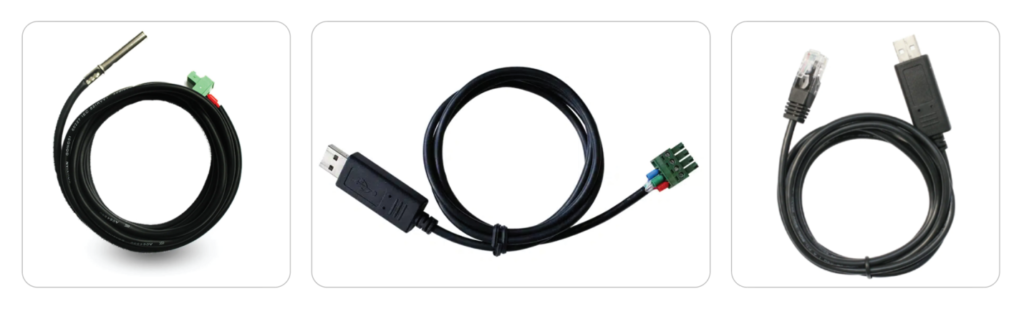
Always there are some accessories connected to the charge controller, battery, and inverter via some sort of cable for monitoring, controlling, and configuring the system. These cables just carry a very small amount of current like 0.5 amps and even less.
Off-grid inverters offer two different configurations for the DC input and AC socket placement. The first configuration is the Separate DC Input and AC Socket Configuration, which can be found in models like IPT2000, and IP1500-42Plus. In this configuration, the DC input and AC sockets are located on opposite sides of the inverter.
The second configuration is the Combined DC Input and AC Socket Configuration, which is available in models like IPT3000-12. In this configuration, both the DC input and AC sockets are situated on the same side of the inverter.
| Cookie | Duration | Description |
|---|---|---|
| cookielawinfo-checkbox-analytics | 11 months | This cookie is set by GDPR Cookie Consent plugin. The cookie is used to store the user consent for the cookies in the category "Analytics". |
| cookielawinfo-checkbox-functional | 11 months | The cookie is set by GDPR cookie consent to record the user consent for the cookies in the category "Functional". |
| cookielawinfo-checkbox-necessary | 11 months | This cookie is set by GDPR Cookie Consent plugin. The cookies is used to store the user consent for the cookies in the category "Necessary". |
| cookielawinfo-checkbox-others | 11 months | This cookie is set by GDPR Cookie Consent plugin. The cookie is used to store the user consent for the cookies in the category "Other. |
| cookielawinfo-checkbox-performance | 11 months | This cookie is set by GDPR Cookie Consent plugin. The cookie is used to store the user consent for the cookies in the category "Performance". |
| viewed_cookie_policy | 11 months | The cookie is set by the GDPR Cookie Consent plugin and is used to store whether or not user has consented to the use of cookies. It does not store any personal data. |