Inverter Charger Parallel Operation Tutorial
- 22 January 2024
- 3039 views
- No Comments

This parallel connection guide is designed to assist users with the parallel operation of HP series inverter chargers, capable of both single-phase and three-phase parallel configurations. We will check the specific connection methods for each model, while comprehensive details can be found in the respective user manuals.
1. Preparation for Parallel Operation
1.1 Selecting the Right Wire and Breaker Sizes
· For Single Inverter/Charger Connection:
· Recommended battery wire and breaker sizes are specified for each model, such as the UC3522-1250P20 and HP5542-AH1050P20SA, requiring a 35 mm2/2AWG wire with a 2P—200A circuit breaker. Other models like the HP3541-AH0625P65A need a 20mm2/4AWG wire with a 2P—125A circuit breaker.
Please refer to the table in Appendix 1 for more information.
· For PV, Utility, and AC Output Wires:
· The sizing for PV, utility, and AC output wires, including breakers, remains the same as for single installations. Refer to the product model’s user manual for appropriate wire and breaker size selection.
1.2 Key Considerations for Parallel Installation
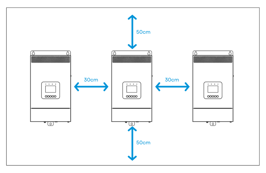
· Installation Location:
· Ensure proper air circulation for heat dissipation, maintaining about 30cm of clearance on the sides and approximately 50cm above and below the unit. Install all units on the same level for optimal operation.
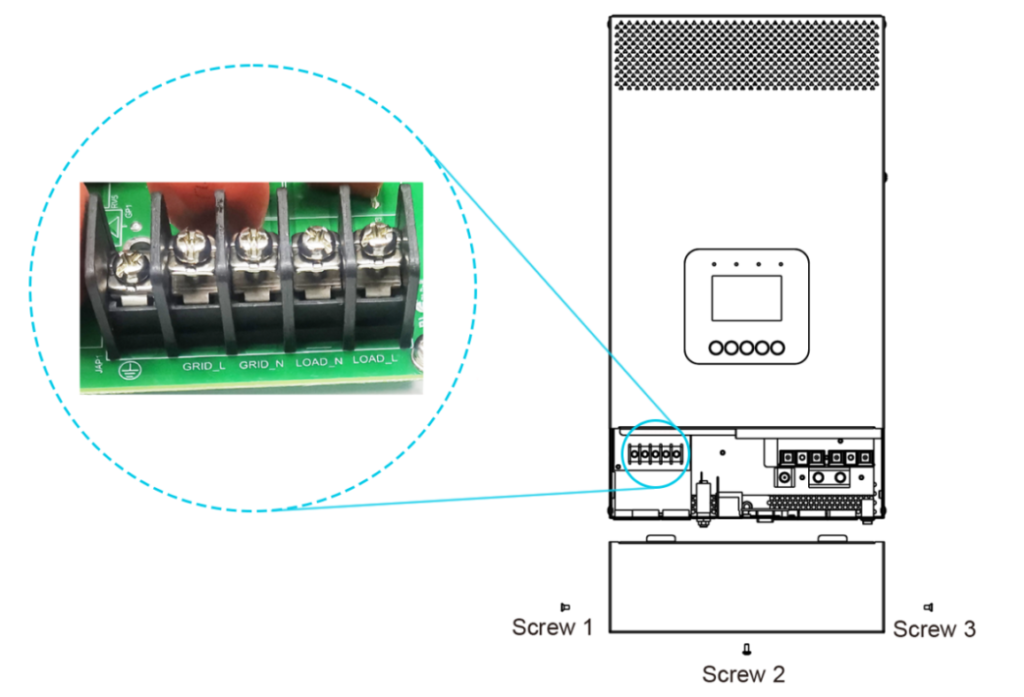
· Wiring Procedure:
· Begin by removing the wire cover, which is secured by three screws. This step is crucial for safe and efficient wiring.
Note: The wiring diagrams and installation instructions provided here use the HP-AHP20SA as a reference model. However, the parallel wiring concept is similar across different models. Always refer to the actual product you have for precise installation guidance.
2. Single Phase Parallel Operation
2.1 Diagram for Single Phase Parallel Wiring
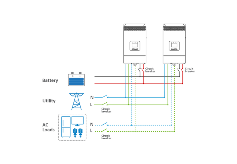
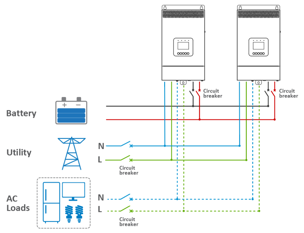
2.1.1 Establishing Connections for Battery, Utility, Load, and Parallel Communication
· Two Inverters:
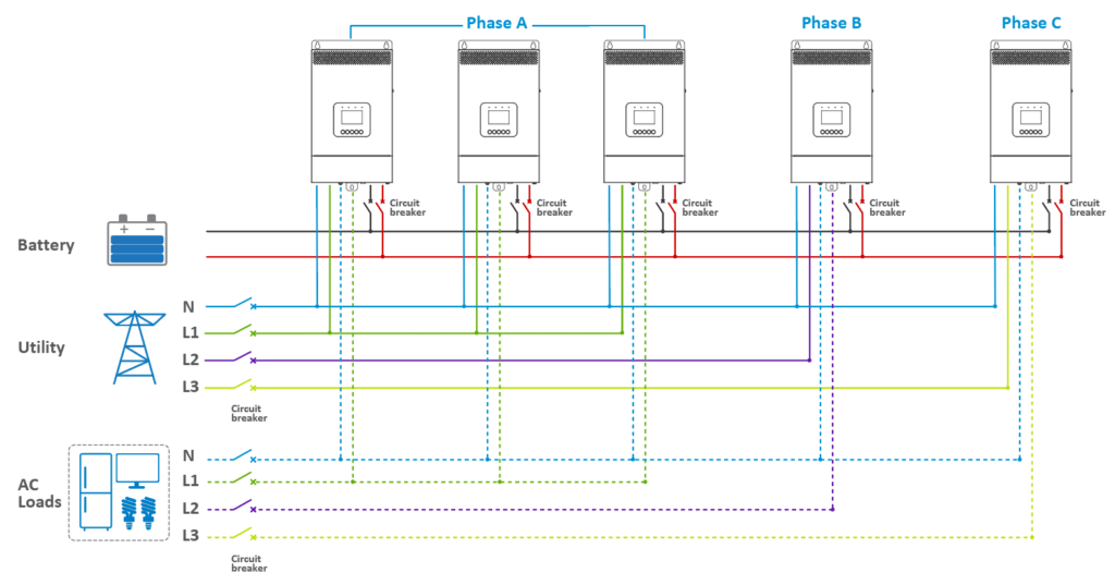
· Connect the battery, utility, and load as per the diagram for the “BATT Input Mode > Shared” setting.
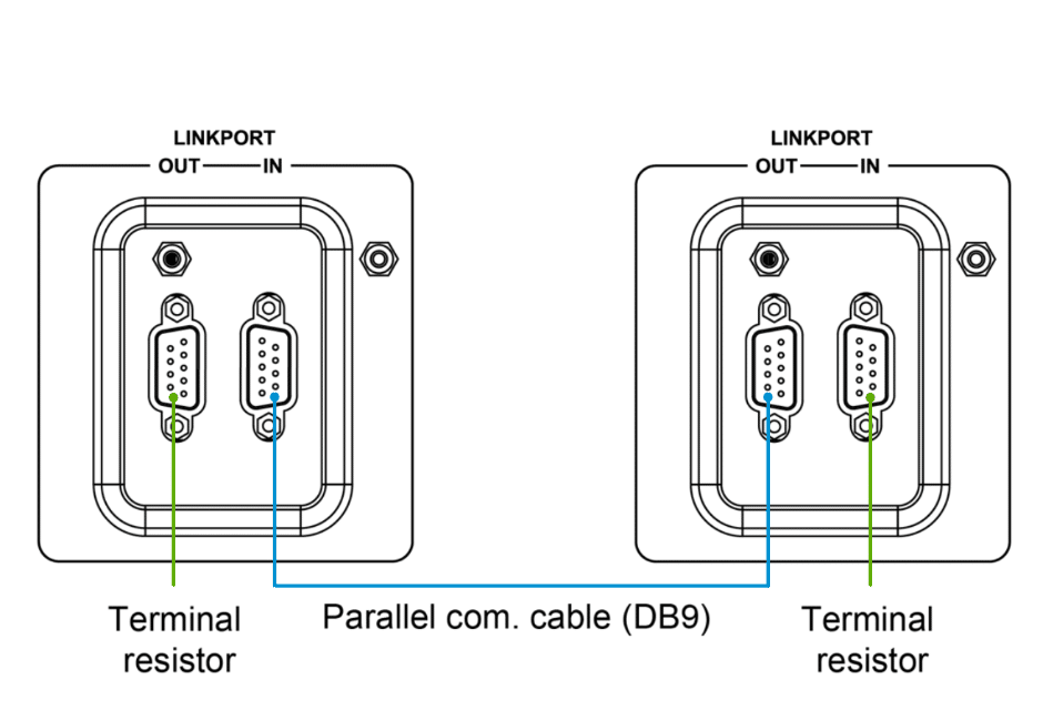
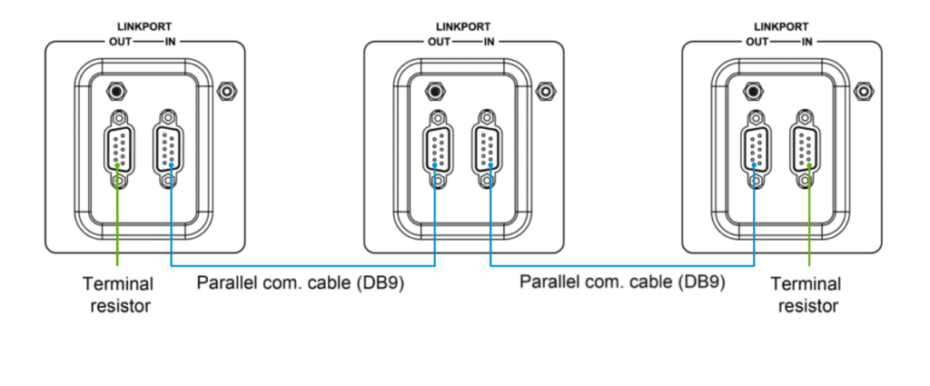
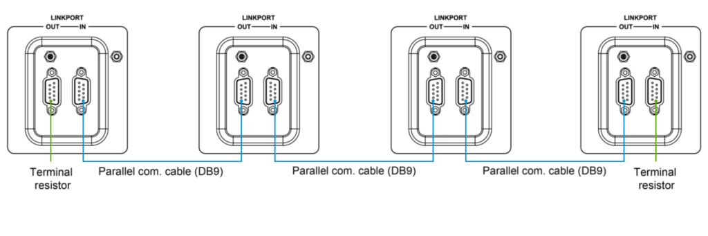
· Link the parallel communication ports (DB9 ports) on each inverter/charger using the parallel communication cables.
· Attach the CAN bus terminal resistor (DB9 connector), an included accessory, to the DB9 ports of the first and last inverter/charger in the setup.
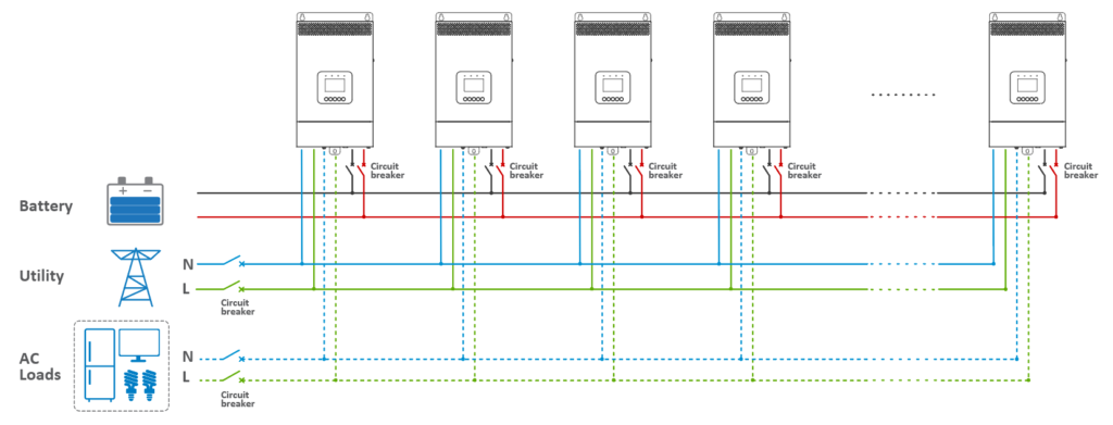
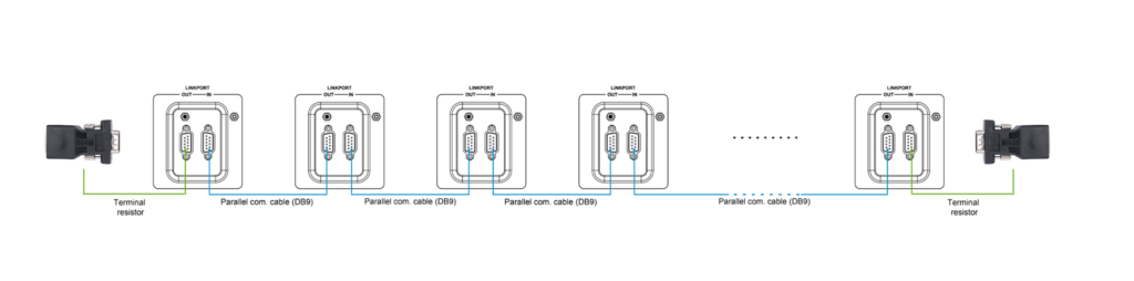
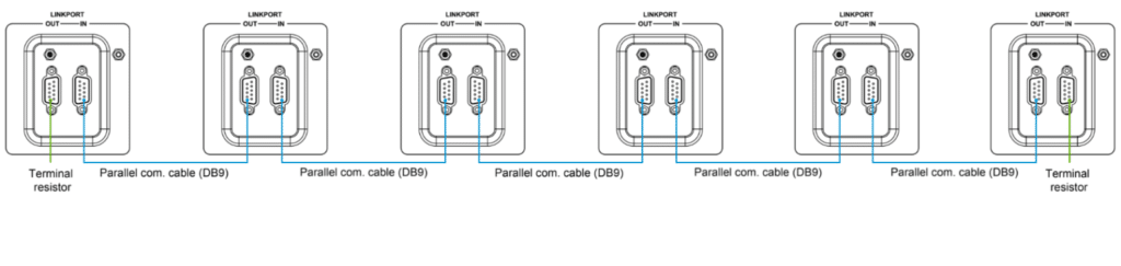
· Configuring Three or More Inverter/Chargers in Single Phase Parallel:
· Follow similar steps as above for connecting the battery, utility, load, and setting up the parallel communication cables. Remember, the diagram and instructions apply to the “BATT Input Mode > Shared” configuration. For a higher number of inverter/chargers, or in the “Independent” mode, adjust connections accordingly.
2.1.2 Connecting Photovoltaic (PV) Panels
· The process for connecting PV panels in a parallel system mirrors that of a single inverter/charger setup. For specific guidelines on how to connect PV panels in a parallel configuration, consult the user manual of the respective inverter/charger model. These manuals provide detailed instructions for PV connections in both single and parallel inverter/charger systems.
3. Three Phase Parallel Operation
3.1 Diagram for Three Phase Parallel Wiring
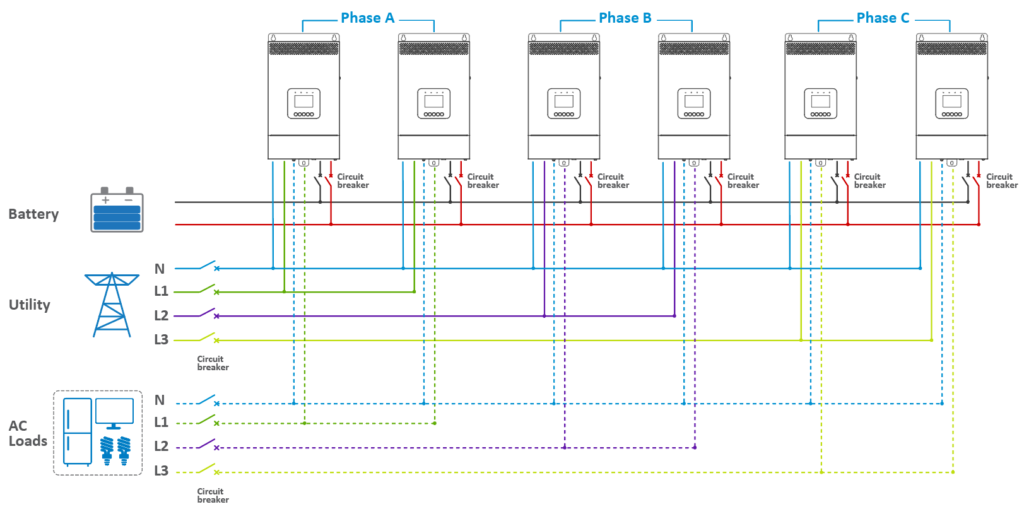
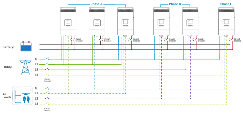
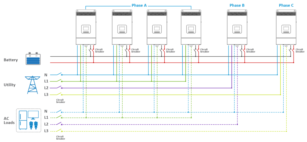
· In a three-phase parallel setup (consisting of Phase A, Phase B, and Phase C), users have the flexibility to determine the number of parallel units in each phase. This allows for the customization of capacity per phase based on specific requirements. For instance, a user might configure four inverter/chargers for Phase A, while allocating only one each for Phase B and Phase C. Regardless of the number of units in Phases A, B, and C, the wiring approach remains consistent across all three phases. This modularity in configuration ensures versatility in addressing diverse power needs.
3.1.1 Connecting the Battery, Utility, Load, and Parallel Communication Cables
For configurations with different numbers of inverters per phase, the approach involves:
· For Two Units Each in Phase A, B, and C:
· Connect the battery, utility, and load as per the “BATT Input Mode > Shared” or “Independent” settings.
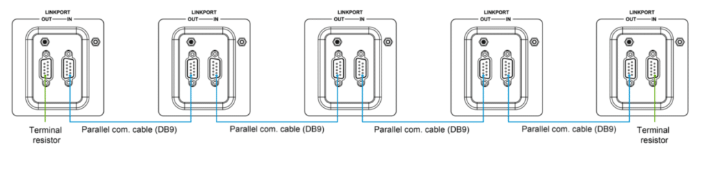
· Use the parallel communication cables to connect the DB9 ports on each inverter/charger.
· Attach the CAN bus terminal resistor (DB9 connector) to the DB9 ports of both the first and last inverter/charger in the arrangement.
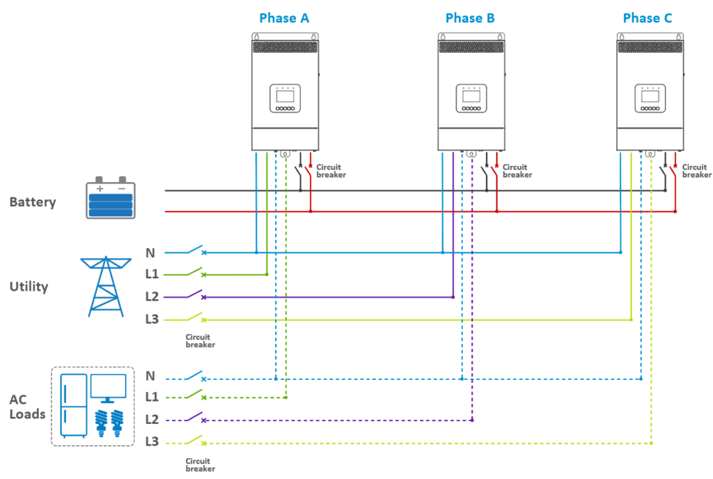
· For One Unit in Phase A, B, and C:
· Connect the battery, utility, and load. Note that the diagram refers to the “BATT Input Mode > Shared” setting. For the “Independent” setting, each inverter/charger must be connected to its own separate battery pack.
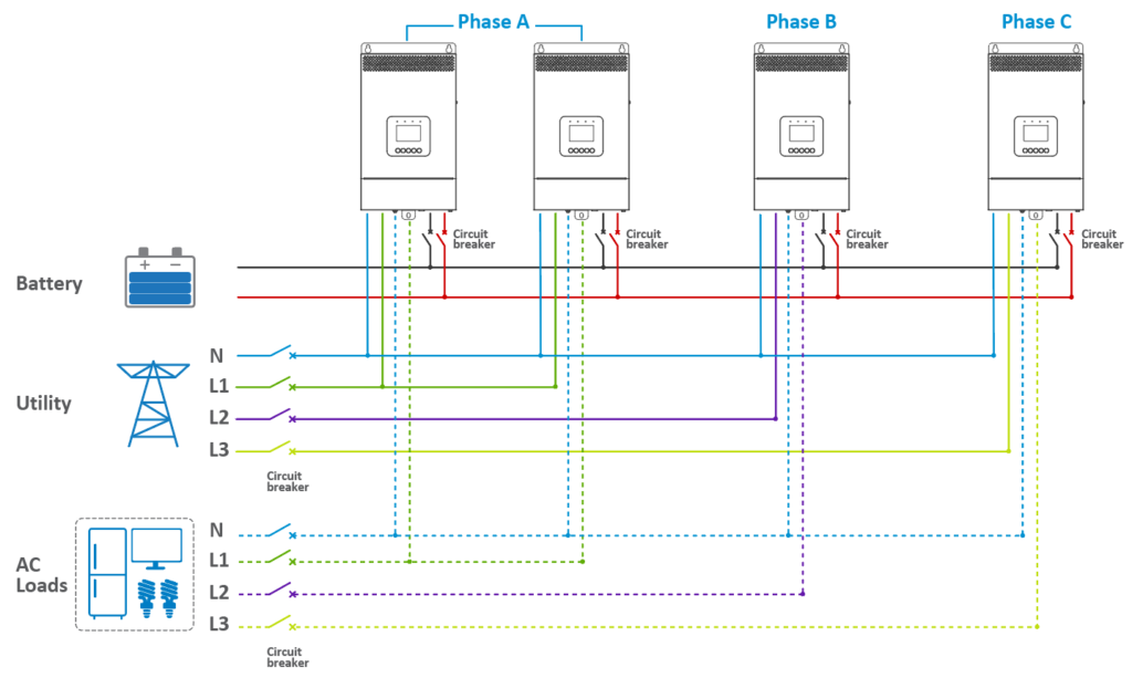
· For Two Units in Phase A, One in Phase B, and One in Phase C:
· Follow the same connection method as outlined above, adjusting the number of units per phase accordingly.
· For Three Units in Phase A, One in Phase B, and One in Phase C:
· Connect each phase following the same procedure, ensuring the appropriate number of units for each phase.
· For Three Units in Phase A, Two in Phase B, and One in Phase C:
· The connection method remains consistent, with adjustments made for the number of units in each phase.
· For Four Units in Phase A, One in Phase B, and One in Phase C:
· Connect the battery, utility, and load according to the number of units allocated to each phase, following the same overall connection strategy.
3.1.2 Connecting PV Panels
· The method for connecting PV panels in a parallel system is the same as in a single inverter/charger configuration. For detailed instructions on PV panel connections in a parallel setup, refer to the user manual of the specific inverter/charger model, which includes comprehensive guidelines for both single and parallel connections.
Appendix 1: Wire and Circuit Breaker Specifications for Various Inverter/Charger Models
Battery wire size | Circuit breaker | |
UC3522-1250P20, UCP3522-1250P20 KR3522-1250P20, KRP3522-1250P20 HP3522-AH1250P65A | 35 mm2/2AWG | 2P—200A |
HP3542-AH0650P20SA, HP3542-AH0650P30A HP3541-AH0625P65A UC3542-0650P20, UCP3542-0650P20 KR3542-0650P20, KRP3542-0650P20 KP3542-AH0650P20PS, HP3542-AH0650P65A | 20mm2/4AWG | 2P—125A |
HP5542-AH1050P20SA, P5542-AH1050P30A HP5542-AH1050P65A UC5542-1050P20, UCP5542-1050P20 KR5542-1050P20, KRP5542-1050P20 KP5542-AH1050P20PS, KP5542-AH1050P20PD | 35 mm2/2AWG | 2P—200A |
| Cookie | Duration | Description |
|---|---|---|
| cookielawinfo-checkbox-analytics | 11 months | This cookie is set by GDPR Cookie Consent plugin. The cookie is used to store the user consent for the cookies in the category "Analytics". |
| cookielawinfo-checkbox-functional | 11 months | The cookie is set by GDPR cookie consent to record the user consent for the cookies in the category "Functional". |
| cookielawinfo-checkbox-necessary | 11 months | This cookie is set by GDPR Cookie Consent plugin. The cookies is used to store the user consent for the cookies in the category "Necessary". |
| cookielawinfo-checkbox-others | 11 months | This cookie is set by GDPR Cookie Consent plugin. The cookie is used to store the user consent for the cookies in the category "Other. |
| cookielawinfo-checkbox-performance | 11 months | This cookie is set by GDPR Cookie Consent plugin. The cookie is used to store the user consent for the cookies in the category "Performance". |
| viewed_cookie_policy | 11 months | The cookie is set by the GDPR Cookie Consent plugin and is used to store whether or not user has consented to the use of cookies. It does not store any personal data. |